
This is a collection of stuff that we get asked all the time. Little things that can make a world of difference to your SR. Things you can do yourself instead of having to pay somebody else. I'll add pics (and more information) as time permits.
On this page
- 1. IGN timing adjustment
- 2. Throttle Position Sensor
- 3. Fuel Pressure Regulator
- 4. Idle Adjustment
- 5. Vacuum Lines
- 6. Fitting a Consult Port
- 7. Z32 Airflow Meter fitment
- 8. Fuel Pumps 101
- 9. Cleaning your Airflow Meter
- 10. Changing Injectors
- 11. Blow-off Valves
- 12. Wideband AFR Gauge
- 13. Misc
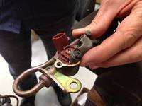
1. IGN Timing Adjustment
Sounds simple but it's amazing how many people mess this up. Firstly there are two different ways to place the pickup. Nissan have provided a loop in the wiring loom that drives coil No. 1. You'll find it hanging out of the loom right at the back of the head - near the firewall. Try this one first - just hook the sensor of your timing light through the loop. I've got an old crusty timing light and this loop works fine with it. Other people have had trouble using the loop and prefer to sense directly off of No. 1 plug by making a plug lead extension. Seems the basic timing lights work best with the loop - the "dial-back" lights need to take signal direct from the plug as they are more sensitive and can false trigger on the wrong edge of the signal.
Prerequisites:
-
Engine must be at normal operating temperature.
-
Idle speed must be correct. Nissan ECU's use IGN timing to trim idle speed. If idle speed is too low the ECU will add timing, if it's too high then it will pull timing back. In reality timing affects idle speed - and idle speed affects timing. So you sometimes need to go back and forth between the two adjustments to get them both right.
-
ECU must be seeing "TPS Closed". This is a flag which is set inside the ECU when the throttle is closed. Some engines use a switch on the TPS to provide this - SR20 ECU's simply look for a certain voltage on the TPS (Throttle Position Sensor). Refer to TPS Adjustment section. The ECU will only access the idle tables when the TPS Closed flag is set. If this is not happening then it uses the main timing maps to determine IGN timing - this will not give us the 15 degrees we're looking for.
Without laptop: Nissan say to disconnect the TPS to lock the timing but I've not had a lot of success using this method. The other way is to hold the throttle open very slightly (TPS Closed flag must still be set) to increase revs a bit. So timing light in one hand, throttle in the other. You'll see the timing mark jumping around at idle and then when you increase revs to 1100 or so it will suddenly stabilise. This should be 15 degrees and this is when you take your reading. Don't rev it too much or you'll see timing start to increase.
With laptop: The only reliable method is to monitor the timing directly from the ECU via the Consult Port. You'll need a Consult Cable, a laptop and some monitoring software. I use Datascan software for this. Then you just watch the reported timing value live on the screen and adjust your Crank Angle Sensor until what you're seeing on the crank pulley (with your timing light) matches what's on the screen. Datascan also has a handy feature under "Active Tests" called "Base Idle Adjust" - this locks timing at 15 degrees.
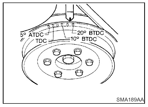
Once you get a reliable reading, set the CAS (Crank Angle Sensor) to 15 degrees. This is a critical adjustment - particularly if your engine has been tuned for more boost etc. Less than 15 degrees will make it very sluggish. More gives extra power but may lead to detonation and subsequent engine damage. Note also that the timing marks start at -5 degrees so 15 is the 5th mark from the left. It pays to mark it with some white-out or brightly coloured paint. Base timing on most SR's is 15 degrees - a notable exception is the RNN14 which uses 20 degrees.
 |
2. Throttle Position Sensor
As the name suggests this lets the ECU know how far open the throttle is. Although this is not the primary load sensing device, it can upset things pretty badly if it's faulty or not adjusted correctly. It consists of a potentiometer (just like a volume knob) that rotates as the throttle is opened and closed. It has 3 pins. The ECU feeds 5V to one, 0V to the other and a voltage somewhere in between is picked off and sent back to the ECU. This signal is used to calculate throttle opening speed, throttle position and to sense when the throttle is closed so the ECU can provide a smooth idle.
Adjustment : This can either be done manually (with a multimeter) or by plugging into the Consult Port with a laptop and reading it straight off the screen. If using a multimeter it must be done with IGN ON (engine does not need to be running) and the connector fitted to the TPS. You'll need nice sharp multimeter probes to pierce the insulation on the wires - it often pays to give them a quick sharpen with a file/grinder etc. Carefully probe the 0V wire (Black) and the signal wire (White). Don't use chassis GND. With throttle closed you should be seeing 0.5V. The spec is 0.35V to 0.65V but it's good to have it right in the middle. Adjustment is done by loosening the 2 screws that mount the TPS - NOT by using the throttle stop screw.
TPS Closed :Check that the ECU is actually seeing "TPS Closed". It monitors the TPS position and when it's in a certain range (normally 0.35 to 0.65V) it assumes the throttle is closed. This triggers a flag in the ECU which makes it go into idle mode. You can monitor this via the Consult port using a laptop. If your throttle is closed but the ECU doesn't see it, then stable idle will be impossible to achieve. Some ECU's will learn where TPS Closed is by checking the value at startup. After a few starts (with throttle closed) the ECU will assume that the voltage it's seeing is TPS Closed and the TPS Closed flag will be set.
Check TPS function : While you're playing with the TPS it's a good idea to check it across the range. Slowly open the throttle - you should see the voltage increase smoothly to just over 4V. If you see any sudden changes (to 0V or 5V) then the TPS must be replaced. The Consult Port is extra handy for doing this check as you can log the TPS value while you drive the car - and then check the trace for any drop-outs later.
Autos : These use a different TPS. It has 6 wires. Half of it still functions the same as the manual 3 pin TPS - so all of the above still applies (wire colours are different but you still need to measure between the Black and White wires). The other half has switches (for throttle fully closed and fully open) which go to the auto trans to determine shift points. The TPS in auto vehicles is notoriously unreliable. When the auto trans half goes faulty the trans will not shift correctly. Unfortunately the main TPS part also goes bad very quickly. They suffer from moisture ingress. Once this happens a replacement TPS is required. If you've converted to a manual trans then it pays to also convert to a manual TPS for reliability's sake. They bolt up but you'll need to replace the 6 pin TPS connector and replace it with a 3 pin manual TPS connector. You only need the White (signal), Light Green/Black (5V power) and Black (return) wires. Snip the others off.
3. Fuel Pressure Regulator
Not much to this one - but it's quite important. What you need to know is that the FPR regulates the fuel pressure based on manifold pressure. So it relies on having a "sense line" so it can see manifold pressure. This is just a short length of hose. So far so good. So as boost rises, so does fuel pressure. If you think about this, it has to - because the injectors are firing their fuel into the manifold. The system is set up so that the injectors deliver their fuel at 3 bar (43.5psi). But if they are firing fuel into a manifold that has been pressurised to (say) 10psi by Mr Garrett then they are facing an uphill battle. So what happens is that with 0 psi boost the fuel pressure is 43.5 psi. For each psi of boost, the fuel pressure increases by 1 psi - keeping the pressure difference across the injectors constant - this is called a "linear rate" FPR. So at 10 psi boost the fuel pressure should be 53.5 psi
Where this all goes astray is if something happens to that little piece of hose. This is why it is recommended to take the source for your boost gauge/EBC from somewhere else. If you tee into the hose going to the FPR and a leak develops somewhere in your boost gauge/EBC then the FPR won't get the correct boost signal. Then fuel pressure will be low and your SR will lean out. Then bad things happen - combustion temps increase, detonation starts and the next thing you know you've got bits of SR all over the shed and you're pricing engine components.
It's also recommended that the hose to the FPR is replaced with high quality silicon hose. Get the nice thick wall hose if you can. Cheap insurance.
For those who are tuning their engines using the factory ECU - stick with the factory FPR unless you have a good reason to change. They work perfectly well. If you have a huge fuel system and the factory FPR cannot bypass enough fuel (ie: fuel pressure is always too high) then make sure you buy a "linear rate" FPR (ie: fuel pressure increases 1 psi for each 1 psi of boost). Do not under any circumstances fit a "rising rate" FPR (ie: fuel pressure increases more than 1 psi for each 1 psi of boost). You will create your very own personal tuning hell.
4. Idle Adjustment
If you've just installed an SR and the idle speed isn't right then you may be tempted to go for the idle adjustment. Before you do consider this : unless the engine is a real clunker then there's a pretty good chance that the idle was spot on before it was removed. So the idle problem is more than likely due to a fault with the installation. By trying to adjust the idle you will just cover up the symptoms. Check all your hoses around the inlet area first. Any air leak into the manifold will increase idle speed.
Adjustment is not as obvious as it might seem - particularly if you're used to old school carby engines. See the throttle stop screw on the throttle body? Don't touch it. The idle is controlled by the AAC valve (Auxiliary Air Control). This valve simply bleeds air around the throttle body. It's mounted on the inlet manifold and you will find an adjustment when you peer down between the runners of the manifold on the S13 - slightly different on S14/15 but easy enough to find. Standard idle speed is 825rpm when warm.
The purpose of the throttle stop screw is to prevent the throttle butterfly from sticking in the bore. Adjustment is not normally required but may be performed by backing off the stop screw until you feel the butterfly start to stick in the bore, then screw the stop screw inwards until the butterfly is totally closed but isn't sticking in the bore. Then tighten the lock nut.
If you're setting your idle from scratch then there are a few things you need to know about. A good place to start is probably how the ECU controls idle. To work out that the engine is trying to idle it monitors the TPS voltage to see if the throttle is closed. This should be around 0.5V. Once this happens the ECU sets the "Throttle Closed" flag (this flag can be monitored using any of the diagnostic packages available). If this flag isn't being set then the ECU does not know that the engine is trying to idle and it will not try to maintain target idle speed. It opens/closes the AAC valve to allow more/less air into the engine. It will also adjust ignition timing to trim idle higher/lower. At target idle you'll see 15 degrees, if idle is too high you'll see less than 15 and if idle is too low the ECU will try to increase RPM by adding timing.
Once you're happy that everything is in order you can monitor the AAC valve signal (using Datascan etc.) and see how close you've got it. With engine warm the AAC valve signal should sit around 50%. If not, adjust the idle screw on the idle control valve until it does. At 50% the ECU can adjust up/down to trim idle speed as required.
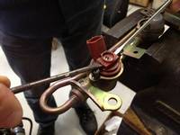
5. Vacuum Lines
Details vary between models but the basic concepts are the same.
-
One line from boost source to wastegate actuator as mentioned above. Keep it pre-throttle body as the WG actuator is not designed to operate with vacuum.
-
One line from inlet manifold to Fuel Pressure Regulator. This one is very important. Don’t tee anything else off of here. Use good quality silicon hose and even put clamps on each end. Failure of this hose = dead engine. (see FPR)
-
One line from inlet manifold to BOV. Either of the fittings under the TB will do.
-
One big (15mm?) line from pre-TB to Idle Air Control Valve. This may or may not already be hooked up. You basically just need an air source that has been through the airflow meter into the IACV. On these engines the TB is totally closed at idle. All idle air gets to the engine via the IACV. So if you need to adjust idle (you shouldn’t have to) then do it on the IACV – not the TB. Usually there’s a fitting in the factory plumbing that hooks this line in just before the TB.
-
Some of the hoses you'll see will be for the factory charcoal canister. On some engines the canister is over the LHS and so you have a bunch of lines that run across the top of the rad from the RHS of the engine. Only required if your conversion needs to pass emissions regs.
6. Consult Port
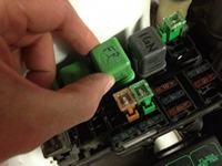
Usually when you buy an SR wiring loom it will be missing the Consult Port. This is because the Consult Port is part of the body loom - the plug will normally be around the fusebox inside the car. You really need this part if you are serious about having your SR run right. Without it you are really in the dark.
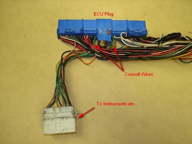
They are not hard to fit either. The easiest way is to grab one from a wreck. Most Nissans from around 1990 to 2000 had them. Snip the plug out with about 200mm of wire if possible. Then it's just a matter of wiring it into your loom. You need 5 wires - 12V, GND, CLK, Receive and Transmit (no CLK on S15). Consult signals can be found on the main ECU connector near the bolt in the middle (see below for diagrams). They run from here to a small white plug about 150mm away on S13 or 300mm away on S14/15. This plug normally plugs into the body loom and contains signals that go from the ECU to the dash.
 |
Snip the wires near the white plug. You need the Green (Tx), Green/white (CLK) and Green/black (Rx) wires. On the S13 there's also a black GND wire on the white plug - so snip it too. Now you just need a power wire. Best way is to just splice into the ECU power. These are the black/white wires near the end of the connector. Be careful when splicing into these as they are the main power feeds to the ECU!. |
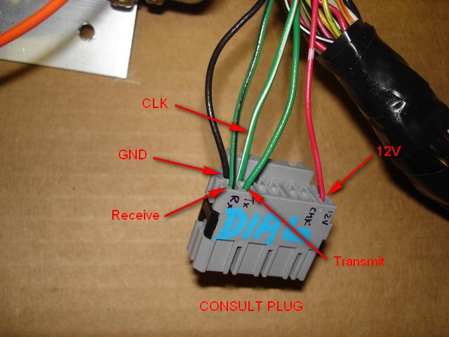 |
Now it's just a matter of getting the signals in the right place. If you've snipped a plug from a wreck then you may have different coloured wires. Don't worry too much about that. As long as you get the wires from the ECU in the right place on the Consult Connector. |
Diagram of consult signal locations for the common ECU's. Drawn looking at wires side of ECU connector.

Now you can plug in and see exactly what's going on in your SR. For more info on how to communicate via the consult port have a look here.
7. Z32 Airflow Meter fitment
It's actually very easy to change your AFM connector to Z32. The pins in the connector for S13/early S14 are the same as Z32. S14a/S15 use different pins, so you'll need to snip off the old plug and either crimp new Z32 pins on - or get a Z32 connector with a length of wire on it and join the wires. For S13/early S14 all you need to do is :
- remove all the pins from the Z32 connector and slip the rubber boot off
- same for the SR connector
- slip the rubber boot from the Z32 connector onto the SR wires
- click the 3 pins on the SR loom into the right positions in the Z32 connector backshell
- re-fit the rubber boot to the connector backshell
Result : perfect job that looks like factory. Not tape, no soldering. 5 minute job.
Downside : the pins can be a bugger to remove if you don't know what you're doing. Use a small jeweller's screwdriver to depress the little locking tangs - and be patient. If you pull too hard on the wires without pushing the little tang in from the other side you will wreck the backshell and the pin. Double check that you have the wires in the right place. Get 'em wrong and smoke will come from your ECU.
Pinouts:

S13
B = 12V (blk/white)
C = GND (blk)
D = Signal (white)

Z32
B = Signal
C = GND
E = 12V
Tip for young players : Z32 AFM's can be finicky buggers. The plumbing between the AFM and the turbo inlet can be critical. Keep the AFM as far as possible from the turbo. And keep the plumbing nice and smooth - no sudden changes of diameter or sharp bends etc. Use an air filter with a bellmouth entry if possible. Use a recirculating BOV and have it enter the pipe close to the turbo and angled towards the turbo. If the AFM is too close to the turbo and/or the plumbing is sloppy you may experience poor return to idle and general grumpiness at idle and low load. This is not some internet rubbish trawled up from a forum - it happens ALL THE TIME!
8. Fuel Pumps 101
Why your fuel pump is critical: It's easy to think that if your fuel pump is faulty then the engine will just run out of fuel and stop. If you're lucky then this is what will happen. If you're not then your fuel pump will just get "lazy". This can be real problem for your SR. If this happens then the pump will still operate but fuel pressure will be low - resulting in lean mixtures (usually at full load). In the case of a non-turbo engine power will be down and if the engine is used continuously at full load it may suffer damage due to detonation and/or valve damage from high combustion temperatures. Often you'll get away with it. Turbo engines are a different story. Mixtures are much more critical with turbos so if they lean out while driven hard then engine damage will happen very quickly.
How do I know if my fuel pump is up to it?
Often the pump will start making more noise than usual. Power will feel a little down - the whole power delivery just becomes "soft". As if the engine isn't really trying. If you can get hold of a WB AFR meter then check the mixtures. Under load a standard SR will run very rich - often richer than 10:1. This is normal. Tuned engines usually run around 12:1. Anything leaner than 12.5:1 should be considered dangerous unless the engine has been specifically tuned for lean mixtures.
The other obvious thing to do is to check your fuel pressure. This is as simple as tee-ing a gauge into the fuel line where it enters the fuel rail.
Make sure you get the line that is supplying the fuel rather than the return line to the tank. Here's what you should see:
Idle = 36psi (this can vary a bit as vacuum at idle sometimes varies)
Atmospheric = 43psi (+/- 1psi)
10psi boost = 53psi
To do the "Atmospheric" measurement you just pull the sense hose off of the Fuel Pressure Regulator (FPR). Pressure with boost applied is calculated by starting at 43psi for 0psi (=atmospheric) and then pressure should rise by 1psi for each psi of boost. So 15psi boost should see 43 + 15 = 58psi fuel pressure. This will either need to be done on a dyno or else you can temporarily secure a pressure gauge to the car (keep it OUTSIDE the cabin!) and have the passenger watch it as you drive.
Often a lazy fuel pump will be capable of supplying the correct pressure at idle and even atmospheric. It's only once boost is applied and the pump is asked to supply higher pressures that they will be found wanting.
9. Airflow Meter Cleaning
Dirty airflow meters are becoming quite common now that most SR's have quite a few k's on them. They become dirty due to normal airborne crud and from oil mist that naturally occurs in the inlet tract. Oiled foam air filters will dirty them quicker than anything else. But nobody uses them anymore (ahem...).
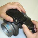
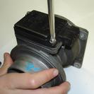
Symptoms can be hard to fathom as sometimes they will cause the engine to run lean, other times rich. I've seen both. Fortunately the sensing elements in SR AFM's are easily removable and quite easy to clean. R32/Z32's can be cleaned but not quite as easily because the sensing elements are not a bolt-in job. Most contamination can be removed using a fine brush (as used for painting models etc.) and solvent such as acetone or contact cleaner.
 |
 |
 |
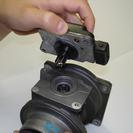 |
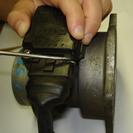
|||||
| Remove clip | Remove connector | Unscrew element | Remove element |
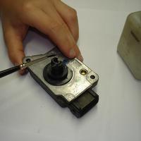 |
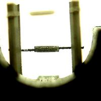
Clean element using a fine brush and solvent. Acetone is good. Or almost any contact cleaner will do. Be careful not to damage the sensing elements. |
| Inspect the two elements under a really good light. An eyeglass helps here (about $5 from Jaycar - the one used in the photo is actually a lens from an old scanner!). They should look like a shiny glass bead with a fine wire wrapped around it. There's often black crud evident. | 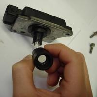 |
 |
Crud = bad. |
| Put it all back together, congratulate yourself on a job well done and shout yourself a beverage for being smart enough to clean your AFM. Instead of declaring it broken and throwing it in the bin like workshops all over the world do. | 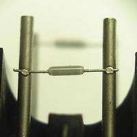 |
10. Changing Injectors
Removal: SR20 injectors can actually be quite difficult to remove if you don't know the technique. Which can result in damage to the injectors, damage to fingers and general bad language. To avoid these nasties try the following technique:
 |
Bleed fuel pressure from the system by removing the fuel pump fuse, relay or wiring to fuel pump with the engine running. It should take a couple seconds before pressure goes to zero and the engine dies. |
 |
Remove screws and retaining cap. |
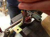 |
Replace screws - screw them in until they just bottom on the fuel rail and then back them off a turn. |
 |
Using 2 small screwdrivers and the screws as jacking posts, lever the injector out. You may need to back the screws out and use the screwdrivers several times before they pop out. |
Replacement: Make sure the O-rings are in good condition before replacing the injectors. It's usually recommended that they are replaced. The top O-rings are usually fine. The bottom ones sometimes need to be replaced. Take a close look at them - if they haven't bounced back to a nice round section or have cracks/nicks/perishing then don't even bother trying to re-use them as they will leak.
Once you have a set of good O-rings then you need to go mad with the lube. You can buy lube specially for this job but if you don't have it then use either Vaseline or engine oil. Lube up the areas on the fuel rail where the O-rings seat, as well as the O-rings themselves.
Then press the injectors into place. It takes a fair amount of force to get them in. Rotate them back and forth as you push. All this lubrication and rotating is an attempt to avoid damaging the lower O-rings. This happens quite easily.
Testing: Once you've got them all in place, fit the caps and it's time for testing. Firstly, turn the IGN on and let the fuel pump prime the system. Then check carefully for external leaks. This part is usually OK. The problem is if the bottom O-rings haven't sealed properly. Unfortunately this is quite common. You can usually tell by the way the engine idles. If it starts up and settles into a smooth idle then things are fine. If the idle is uneven (power is down on one or more cylinders) then there is a problem. Sometimes idle will only be slightly affected and the car will drive fine otherwise. Sometimes they will barely idle.
Diagnosis: The next thing to work out is which O-ring is damaged. This isn't usually too hard to work out. Remove the injector plugs one by one as the engine is idling. You should get a definite change in idle. The one that gives minimum change is the one that's leaking. It gets a bit harder if there's more than one. Another (preferable) technique is to use the "Power Balance Test" in Datascan. This allows you to knock out one cylinder at a time from a laptop connected to the Consult Diagnostic Port.
Stuff you don't even wanna think about: Another problem associated with leaky bottom O-rings is fuel leaking into the cylinder after engine shutdown. EFI systems maintain high fuel pressures after the engine is shut down (as you will know if you've ever removed a fuel hose/injector without first bleeding the system pressure). If a bottom O-ring is leaking then the potential exists for fuel to dribble into the cylinder over time (usually overnight). In the morning the engine will start on 3 cylinders and it will take awhile before the affected cylinder clears. Worst case the cylinder will have enough fuel in it to hydraulic lock. So when it is cranked it simply locks solid. This CAN cause serious engine damage - I've seen bent conrods. This is rare but can happen.
Injector Upgrades: While we're on the subject of injectors, please don't buy drilled out injectors. They're invariably rubbish. Anyone who thinks he can drill the caps as well as the factory is either having himself on or is extremely skilled. I've not met any injectors molesters in the latter category yet. The usual scam is to buy the cheapest injectors available (which generally have very low flow rates) and either drill them out or remove the caps (that create the fine spray pattern) entirely. Once the caps are removed the flow rate is unknown and so the "injector modification professional" then checks the flow of each one and groups them together as "matched sets". This is made to sound like they've carefully matched them to give you a superior quality part. Far from it. The spray pattern is usually massively inferior to the factory injector. So even though the flow rate matches the other injectors, the spray pattern is horrible and so low load/cold start/idle/emissions and fuel economy figures tend to be severely compromised. Avoid anything that mentions "hi-flowed", "modified" or "flow matched".
For SR20 owners it's not too hard to tell good injectors from bad. There is a limited number of side-feed injector manufacturers. Most are made by JECS. This is the company (now owned by Bosch) that makes all the electronic components for most Nissans. They come in a limited number of flow rates. 270cc for most SR20DE's, 370cc (purple) for S13/S14 SR20DET and S15 auto, 480cc (rusty brown) for S15 SR20DET manual. From there we go to 550cc (yellow) and 740cc (red) which are sold by Jap tuning companies HKS, Apexi, Tomei and NISMO. But they're all made by JECS. They all drop in perfectly, the connectors fit and they have 4 precision machine holes in the cap that result in a reliable precision spray pattern. There are some others such as Sard which work OK but are not really made to fit an SR20 - they're made to fit by using a conglomeration of oversized O-rings and adaptor rings. And just when you think the pain is over you find that the connectors are different and you have to snip of your factory connectors. Not good. There are also Blitz 850's now, but I'm not sure on fitment or who makes them.
Beyond that you need to go to a tail-feed setup. This can be a pain to setup but there is a good range of injectors available. Standouts being the Bosch EV14 series and the closely related ID1000's both of which perform brilliantly.
11. Blow-off Valves
| Recirculation valves or Blow-off valves (BOV’s) should always be used. Without a BOV fitted the AFM will see major reversion when the throttle is closed. Air gets stopped by the suddenly closed throttle and then surges backwards through the compressor and out the AFM. Bad for turbo and bad for tuning! The AFM measures airflow the same in either direction so this surge of air creates a burst of fuel at the injectors, resulting in a big rich cough each time the throttle is closed. On cars with auto trans this can easily stall the engine completely. | 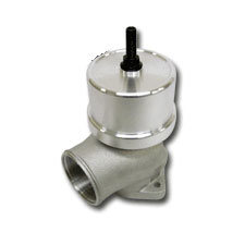 |
Similarly for BOV’s that vent to atmosphere. You don’t get the reversion back to the AFM but the sudden rush of air to atmosphere is still being measured by the AFM so you get the big rich patch on closed throttle. The return air from the BOV should be angled away from the AFM if possible – reducing the risk of airflow backwards into the AFM.
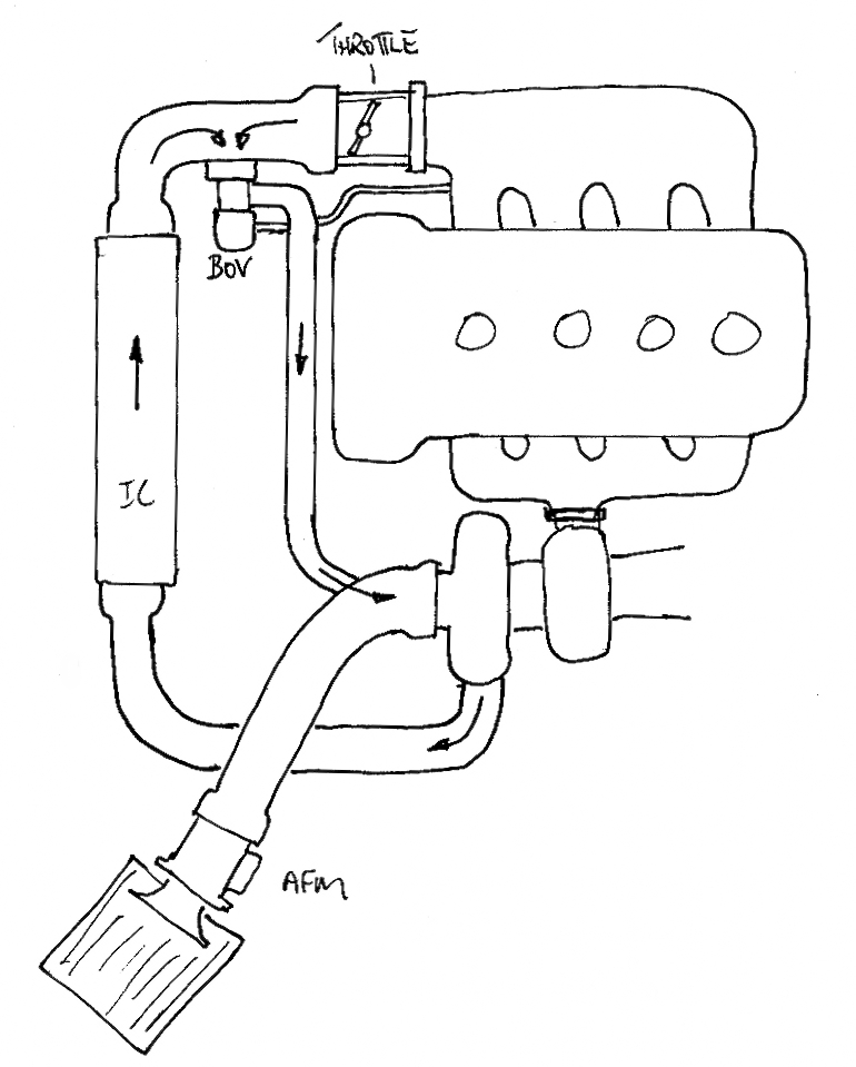 |
Diagram showing normal BOV operation when throttle closes
The stock BOV on most Nissans can actually be made to work very well and hold increased boost with a small modification. So there's really no need to mess with aftermarket BOV's in most cases. Use what Mr. Nissan gave you. Save your money to buy a good set of injectors! Here's a little article I put together for SR20 BOV's
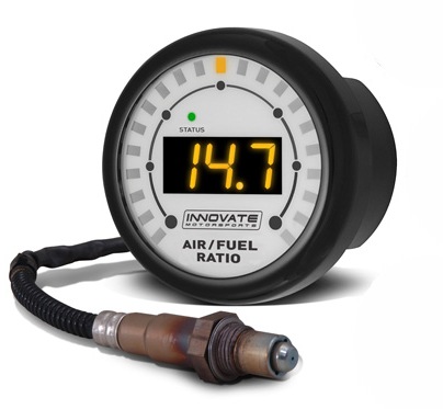
12. Wideband AFR Gauge
A wideband AFR (Air Fuel Ratio) meter is one of the main tools used when tuning turbo engines. Until recently they were considered a specialist tool and had a pricetag to match. So owners would have their engine tuned on a dyno and then drive around confident that everything was right with their engine. And most of the time they were right - to start with anyway. Your tuner probably tuned your engine with an AFR between 11.5 and 12:1 if it's a turbo, or a tad leaner if it's NA. Unfortunately things change - and you'll often have no way of knowing until the damage is done. Particularly if you're one of the big horsepower guys running high boost - if a turbo engine leans out under boost your EGT's (Exhaust Gas Temperature) will increase and you'll do engine damage very quickly.
There are various factors that can change your AFR. The biggest culprit is indubitably fuel pressure. Fuel pressure can decrease for many reasons but the most common are worn fuel pumps and blocked fuel filters. Faulty wiring will also do it. A dirty AFM can also cause your engine to lean out.
So it makes sense to monitor your AFR's. Particularly now that cheap cabin-mount Wideband AFR meters are available. A quick glance occasionally while driving is all it takes to make sure you're still in the safe zone. We've been doing it for years with temperature and oil pressure gauges, so why not keep an eye on our AFR's? It's not that hard once you know what values you should be seeing.
There are many types around but the one that has caught my eye recently is the Innovate "MTX". We've been running Innovate gear for years and they make a decent product. Now with the MTX they've made a fully digital gauge with all the control circuitry built-in - all housed in a 52mm round gauge. This makes them cheaper to produce ($US199 last time I checked - 16May11). Happy days! There's one less excuse for blowing your engine up right there!
 |
13. Misc
Random general interest article on oils. Not many people properly understand the oil they use in their engines. Not good. This is a particularly well written article because it's written at a level that anyone can understand rather than going into full-on technobabble. Enjoy.