Graeme's S15
This car was possibly the rarest of all the S15's - cos was completely standard! But Graeme had plans for it, so we decided it would be nice to get some "baseline data" by putting it on the dyno and seeing what one does as it comes from Mr. Nissan.
Graeme is one of the guys who had been patiently waiting for our "Type 4" NIStune boards to be ready so he could tune the ECU in his S15. We fitted one of the early prototypes to his car and it ran very well. His car is a daily driver so it's the perfect test car, and he kindly volunteered it as a guinea pig.
This is an Australian delivered car. It's well known that we get a de-tuned version of the Japanese cars so the first thing I did was pull the factory maps from the ECU. It's true - our ECU's are de-tuned. Graeme dropped around one day and I reflashed his ECU with the Japanese maps (which I tweaked a bit while I was at it). This made the car a bit more lively. For the record the Japanese maps run a little more IGN timing and the boost control maps run quite different figures - so the main reason they make more power is actually because they run higher boost.
Once on the dyno the usual deficiencies of any standard S13/S14/S15 SR turbo quickly became apparent. Firstly, they are run stupidly rich, and secondly that the factory intercooler is extremely limiting. We actually pointed the big cooling fan on the dyno more towards the side mounted intercooler than the radiator to help. While carefully watching engine temps of course. We had to wait a bit between runs to allow the intercooler to lose its heat. Without this the power would drop off markedly on the second run and any measurement consistency was lost.
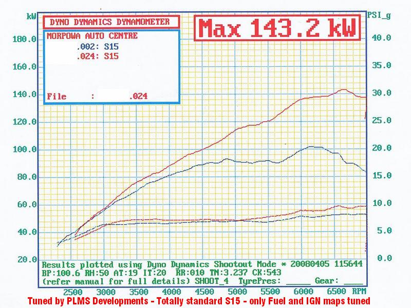
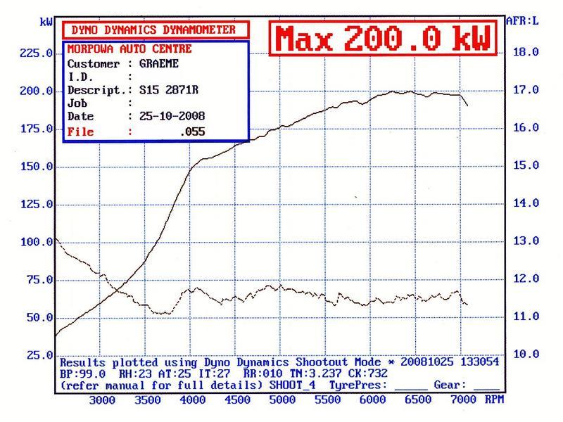
As you'll see by the dyno plots, the AFR's get crazy rich above about 5000 rpm. So rich that the AFR mater bottoms out and we get a flat line after 5000. The result was a pathetic 100rwkw. We were going to stop here as we had our "baseline run" but I couldn't help but get in and adjust the mixtures. What amazed me was the difference it made. Over 40rwkw. And this was without optimising the IGN maps - once Graeme fits the bigger turbo, injectors, AFM and we turn the boost up the IGN maps are going to change a lot so I wasn't going to spend too much time there. I'd flogged Graeme's poor car enough anyway.
 |
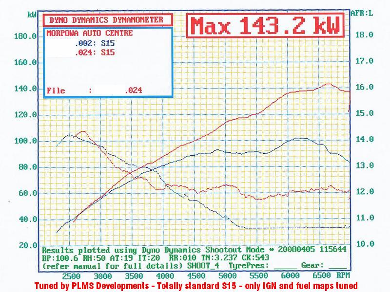 |
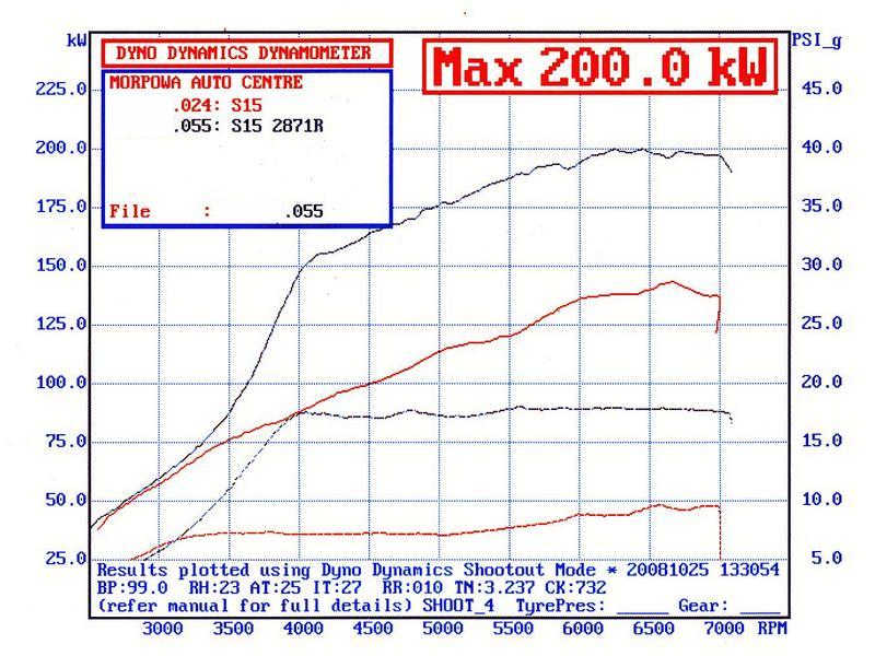
| Power vs boost | Power vs AFR |
This was without touching the boost (all factory boost control parts are still fitted), although with the extra power being developed the boost did creep up a tad up top as you can see by the graph. A lot more could have obviously been had if we'd adjusted boost. But we'd already done more than we intended to anyway.
*** Please note that we did multiple before and after runs to ensure consistency and there were no dyno shenanigans going on. I don't sell tuned chips or anything, so I've nothing to prove. Tuning is merely a sideline that I do cos I love it! ***
A quick road test confirmed the graph. The S15 now has the top end it should have - instead of falling on its face above 6000 rpm.
The really fun part will happen once the upgraded hardware goes on and we turn the boost up!
STAGE 2
Graeme saved his pennies and gathered together a box of gear to take the S15 to the next level. He was very happy with how the S13 SR20 in his Datto 510 went and the temptation to get the same sort of power in his S15 daily driver was just too much. So he first did the usual and upgraded exhaust and added a FMIC. He also found a hardly used 52 trim 2871R and a set of 550's for the right money. The 2871R was fitted up and he drove it around like that (with boost at minimum) for a bit. When we both had some time Graeme dropped around and we fitted up the 550's and Z32 AFM - plus the necessary ECU tuning of course.
The part we were both looking forward to was using the factory boost control solenoid as part of our evil plan. As it turns out this works really well. There are maps in the ECU which allow the boost level to be mapped to RPM. Sweet.
In its stock form the factory boost control solenoid will give you between 8psi (solenoid closed so boost level dictated by spring in wastegate actuator) and around 12psi.
With values of 0 to 10 in the maps the solenoid is closed. Values of 90 to 100 will see the solenoid completely open. Values in between will see the solenoid chattering away at various duty cycle values from 0 to 100%.
OK, so we wanted more than this, so we removed the jet in the hose between the tee and the solenoid. This allowed the solenoid to flow more air, giving higher boost. Boost is then limited by how much the solenoid can flow when fully open. This gave around 16psi. But we wanted more....
The next step was to decrease the size of the jet in the hose that runs from the inlet manifold (boost source) to the tee near the solenoid. The factory jet has a 1.6mm hole. This was decreased to 1.4mm. Max boost was now 20psi. That's more like it!
Values in the boost control maps were then decreased to around 80 - getting us back to between 14 and 16psi. Boost is now programmable between 8 and 20psi. This was all done on the road. Next step is to get it on the dyno for final tune. It'll certainly be nice to be able to adjust the boost level across the RPM band.
Dyno Day
Everything started out great. We had already tried the factory boost control so that was more or less a known quantity. We wanted to see how the boost response of the factory system compared to a Turbotech ball-n-spring valve. As it turns out - pretty damn well!
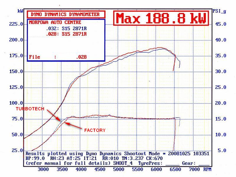 |
On 15psi you can see that there's not a lot in it. Turbotech valve gives a very slight improvement in boost response. Once boost was increased the Turbotech valve suffered from boost drop-off at higher RPM. This is not unusual for these valves. This is where the factory mappable boost control comes into its own. By adjusting the jet size and then changing the values in the boost control maps you can get the boost to rise or fall where you want. |
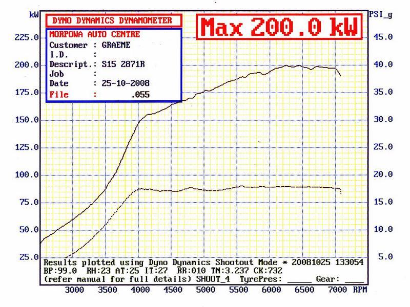
We found that with the 1.4mm jet (that we'd set up previously on the road) the boost would rise to 18psi but then drop off at higher RPM. So we decreased the jet size even further and adjusted the boost control maps to limit boost in the lower RPM region and then increase up top. We finished up with a nice flat boost curve around 18psi - rising slightly towards the top end. Excellent!
The bummer was that it really wasn't making the power we expected. 2871's will usually give around the 200rwkw mark on 16psi. We were running 18psi to achieve the same result. Hmmmm. Most annoying. Research continues....
 |
 |
 |
| Power vs boost | Power vs AFR | T28 vs GT2871R |
Dyno Day 2
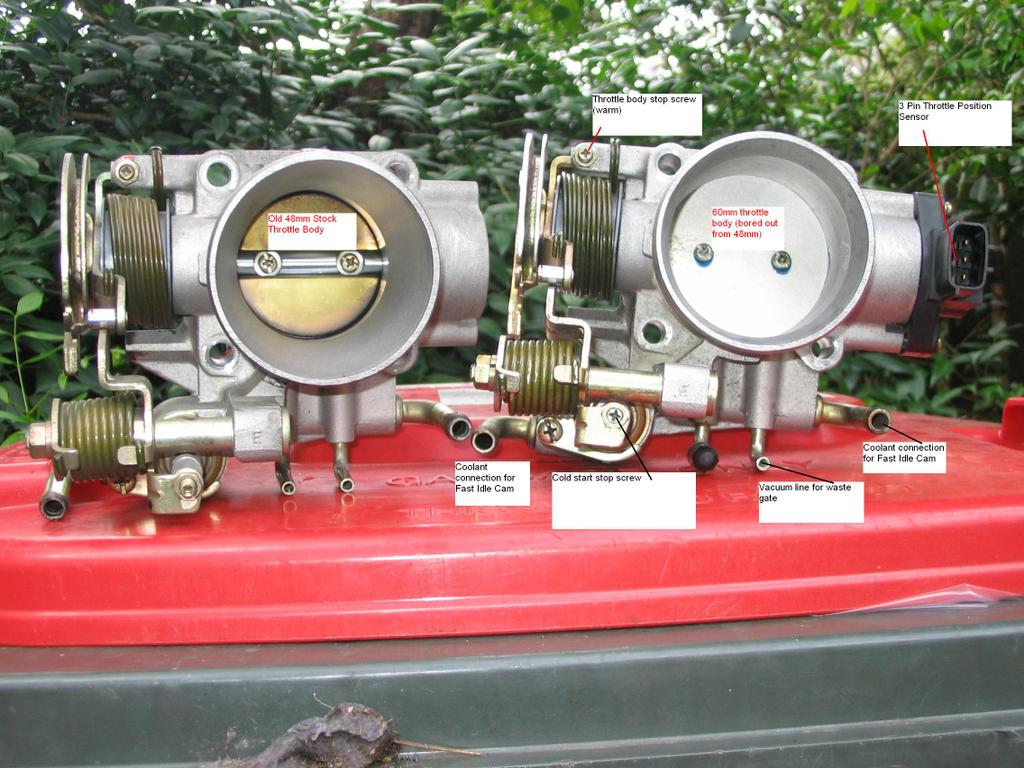
OK, after our first rather disappointing run, Graeme did a few exhaust mods and we were also offered a bored out throttle body (TB) from another S15 owner (thanks Chris). For reasons I never understood the S15 comes with a much smaller TB than the older SR's. There has been much conjecture over whether it's worth increasing the bore to the same 65mm that other SR's run.
 |
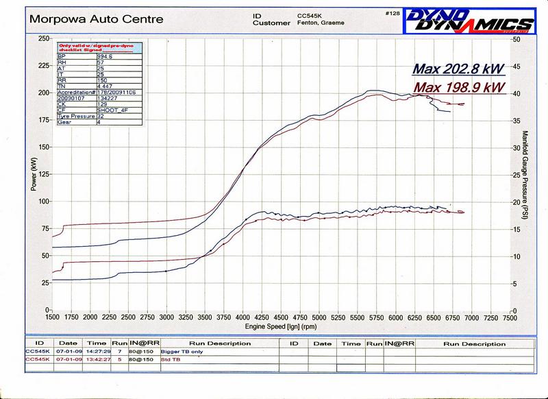 |
| Throttle body mods | Results! |
So we decided to get some figures. We ran the car up on the dyno - first with the old TB and then quickly fitted the bored out TB and ran it up again. The results weren't astonishing but there is certainly a difference. Without touching anything else boost increases by about 1psi. This usually nets around 5rwkw. In this case it gave 4. But it was that kinda day. Please excuse the wobbly dyno curves - it was a brand new dyno and I didn't quite have the hang of setting up the tacho sensing box - so we got the odd bad reading, which results in the squiggles you see on the graph. Throttle body mod photo courtesy Chris Waters.
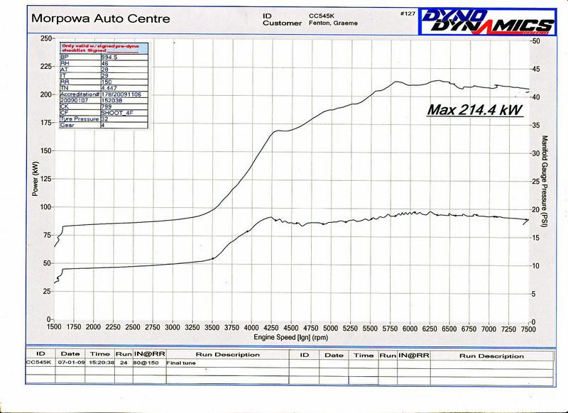 |
After this we spent some more time tweaking the fuel and IGN maps, resulting in 214rwkw. Still a tad down on what it should be, but getting better. The type of rear muffler currently fitted is apparently known to not flow particularly well, so that could well be in for some scrutiny next. |